Graphics Data - Coordinates and Geometry
How coordinate systems, vertices, indices and faces combine into the geometry a GPU can draw.
Geometry is the shape data handed to the GPU: a list of points in space, and instructions for which points join up into triangles. Everything drawn in 3D reduces to this, however curved it looks.
Where This Fits
The data layer, below any particular library. The same structures apply whether you write raw WebGL, use a rendering engine, or write shaders against the result.
Assumes nothing. Read before The Scene Graph and Attributes, Uniforms and Varyings.
Two Origin Points
Most 2D drawing on the web puts the origin (0, 0) at the top left, with Y increasing downwards and coordinates measured in pixels up to (width, height).
3D puts the origin in the centre, Y increasing upwards, coordinates positive or negative.
Screen space                  Cartesian
(0,0) ─────────► x                    +y
  │                                    │
  │      ● (120, 80)          ─────────┼─────────► +x
  │                                    │
  ▼                                    │  ● (0.4, -0.3)
  +y                                  -y
The shift matters because rotation and scaling both happen around the origin. An object at the centre rotates in place; the same object in screen space swings around the corner of the canvas.
A third axis gives (x, y, z), Z running towards or away from the viewer.
Vertices, Indices and Faces
A vertex is a point that carries data. Position is one piece, usually not the only one — a vertex may also carry a colour, a normal, or a UV coordinate. These are its attributes.
Three vertices make a triangle, or face. Every surface a GPU draws is built from faces, because a triangle is the most complex shape guaranteed to be flat.
Vertices live in a flat array. Indices are a second array pointing into the first, so triangles can share vertices instead of duplicating them. A square needs six vertex slots but only four distinct corners:
const geometry = new THREE.BufferGeometry();

const vertices = new Float32Array([
  -1, -1, 0,   //  0  bottom left
   1, -1, 0,   //  1  bottom right
   1,  1, 0,   //  2  top right
  -1,  1, 0    //  3  top left
]);

geometry.setAttribute('position', new THREE.BufferAttribute(vertices, 3));
geometry.setIndex([
  0, 1, 2,   // first triangle
  0, 2, 3    // second triangle, reusing vertices 0 and 2
]);
Drawn as a wireframe, with the four vertices marked:
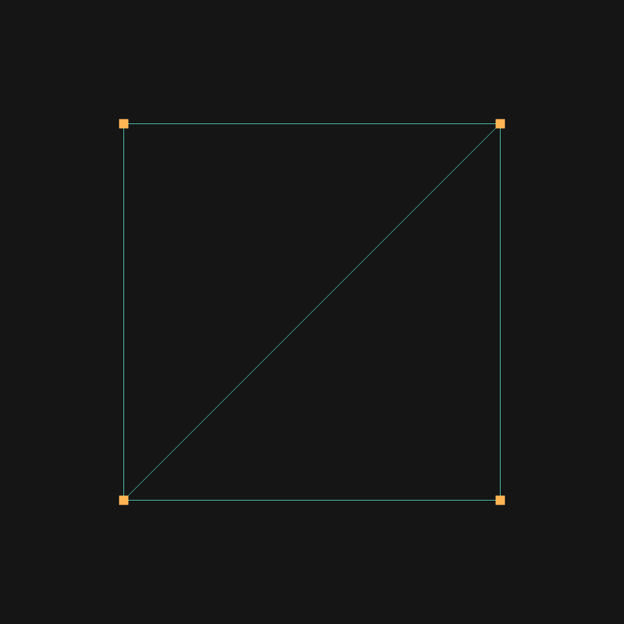
The diagonal is the shared edge. Vertices 0 and 2 each appear in both triangles and are stored once.
On a square the saving is trivial. On a sphere where nearly every vertex is shared between six triangles, it is most of the memory.
Winding Order
The order the three vertices are listed in decides which way a face points. Counter-clockwise is front facing, clockwise is back facing.
Renderers usually discard back-facing triangles without drawing them, an optimisation called back-face culling — the inside of a solid object is never visible, so drawing it is wasted work. Get the winding order wrong on a hand-built shape and it renders inside out, or vanishes from one side.
Geometry
Add more indices in sets of three and you get more triangles, and eventually a cube, a sphere, or anything else.
A geometry holds this vertex data and nothing else. It has no notion of colour or lighting — a sphere geometry describes a sphere’s shape and stops there. Appearance is a separate concern, covered in The Scene Graph.
In practice you rarely build vertices by hand. Rendering engines ship generators for the common shapes that produce positions, normals, UVs and indices for you. Building geometry manually is for when no generator fits, or when the shape is the point of the piece.
See Also
- The Scene Graph — how geometry combines with a material to become drawable
- Attributes, Uniforms and Varyings — how per-vertex data reaches a shader
- Vertex and Fragment Shaders — what happens to each vertex once the GPU has it
Resources
- BufferGeometry — how three.js stores vertex data
Source: WebGL & GLSL — A Primer by Matt DesLauriers